TABLE OF CONTENTS
1 PURPOSE...................…………………………………………………………………2
2 SCOPE........………………..............................................................................................2
3 DEFINITIONS...................…………..............................................................................2
4 RESPONSIBILITY AND AUTHORITY:...………………………............................. 2
5 PROCEDURE………………………………………………………………………….2
6 REFERENCE DOCUMENTS…………………………………………………………2
7 DISTRIBUTION……………………………………………………………………….2
8 RECORDS……………………………………………………………………………..2
9 LINE CYCLE DROPOUT TEST PROCEDURE:.......................... …………………..2
10 TRANSIENT SURGE (RINGWAVE & IMPULSE WAVE) TEST… ……………….3
11 LINE VOLTAGE VARIATION TEST......................………………………………….4
12 HI-POT TEST .............………………………………………………………………... 5
13 OPERATING EXTREMES TEST................…………………………………………..7
14 SOLDER JOINT STRESS TEST.....................………………………………………...7
15 TEMPERATURE TEST (THERMAL SURVEY) .....................………………………8
16 VIBRATION TEST....................................................... ……………………………….11
17 AUDIBLE OUTPUT TEST............................................……………………………... 11
18 BIT GENERATOR ABUSE TEST.....................………………………………………12
19 CALIBRATION VERIFICATION TEST.....................………………………………. 12
20 CHATTERING RELAY TEST ..........................................................………………… 13
21 EMI NOISE TEST........................................ ………………………………………….14
22 ELECTROMIGRATION TEST..................................................……………………… 15
23 ENDURANCE TEST.......................................................................... ………………….15
24 HIGH TEMPERATURE OPERATE TEST........................... ………………………….17
25 LOW TEMPERATURE OPERATE TEST...........................................………………...17
26 MOLD (PLASTIC CHASSIS) STRESS RELIEF TEST……………………………….18
27 OVERLOAD TEST.........................................................................……………………..19
28 OVERVOLTAGE & UNDERVOLTAGE TEST........................……………………….21
29 POWER INPUT TEST .............................………………………………………………22
30 SHIPPING & STORAGE TEMPERATURE TEST................………………………….23
31 RAMP VOLTAGE..........................................................………………………………...24
32 RESISTANCE TO IMPACT (BALL IMPACT) TEST...........………………………….25
33 SPARK INTERFERENCE TEST................................................………………………..27
34 STORAGE HUMIDITY TEST.....................................………………………………….29
35 TERMINAL/CONNECTOR ABUSE......................…………………………………….30
36 UNPACKAGED DROP TEST.........................................……………………………….31
37 ELECTROSTATIC DISCHARGE (AIR OR CONTACT DISCHARGE)……………..31
38 SHOWERING ARC TEST.........................................................................……………...34
39 OPERATIONAL VERIFICATION.........................................................……………….35
40 CONTACT BOUNCE SIMULATION ……………………………………………….. 35
41 REFERENCE DOCUMENTS.........................................................…………………….35
42 DISTRIBUTION……………………………………………………………………… 35
43 RECORDS.......................................................................................……………………. 35
APPENDIX A...................................................................................................………………… 36
APPENDIX B.........................................................................…………………………………. 37
1 PURPOSE
1.1 This document provides detailed work instructions for the tests outlined in the Design Validation Procedure.
2 SCOPE
2.1 This work instruction applies to all personnel responsible for performing Design Validation tests. Applicable personnel may include the Engineering Test Laboratory technicians, members of the Engineering department, or an external certified test lab.
3 DEFINITIONS
3.1 IEC International Electrotechnical Commission
3.2 UUT Unit Under Test
3.3 Testor Personnel responsible for performing Design Validation tests.
3.4 UL Underwriters Laboratories
3.5 CSA Canadian Standards Association
4 RESPONSIBILITY AND AUTHORITY:
4.1 Design Engineering
4.1.1 Provide testor with a detailed test plan specifying the tests to be performed and the numerical quantities of controls to be tested.
4.1.2 Test means and interpretation of results will be evaluated jointly by Quality and Design Engineering.
4.2 Quality Assurance (Engineering/Reliability)
4.2.1 Assist Design Engineering in establishing the validation test plan.
4.2.2 Evaluate test performance jointly with Design Engineering and recommend design and/or process improvements as deemed necessary.
5 PROCEDURE:
5.1 Follow each appropriate individual work instruction as outlined according to the Table of Contents.
6 REFERENCE DOCUMENTS:
6.1 Reference documents are indicated in each individual work instruction.
7 DISTRIBUTION:
7.1 Procedures and work instructions referenced are located as "read-only" files on the ‘S’ drive SYSTEMS.
7.2 Forms are located on the “S’ DRIVEFORMS.
8 RECORDS:
8.1 Records are indicated in each work instruction as "Report"
9 LINE CYCLE DROPOUT TEST PROCEDURE:
9.1 PURPOSE
9.1.1 To evaluate the effects of power line drop-out on control operation, and to determine drop-out duration control can withstand.
9.2 EQUIPMENT
9.2.1 AC Drop-out Simulator, Variac, and Oscilloscope
9.3 PROCEDURE
9.3.1 Record serial numbers of devices to be tested, along with critical to operation information.
9.3.2 Plug the Variac into a power source, plug the Drop-out Simulator into the Variac, and connect the device under test to the Drop-out Simulator.
9.3.3 Set the oscilloscope up to monitor the power-on-reset circuit of the device under test.
9.3.4 Adjust the Variac to the specified low line condition.
9.3.5 Power up the control and verify that it is functioning properly.
9.3.6 Starting with a low number of drop-out cycles and incrementing in half cycle increments, drop-out power to the control.
9.3.7 Observe the response after every drop-out.
9.3.8 Continue to increase drop-out length until control resets, or cancels, a programmed mode.
9.3.9 At this point record number of AC cycles of drop-out, and waveform of power-on-reset circuit.
9.3.10 Repeat this test for all control modes, at low, nominal, and high line voltages.
9.4 REPORT
9.4.1 Lab Report Form
10 TRANSIENT SURGE (RINGWAVE & IMPULSE WAVE) TEST
10.1 PURPOSE
10.1.1 To evaluate the effects of transient energy on control operation.
10.2 REFERENCE
10.2.1 UL858A Second Edition dated 2/22/95.
10.3 EQUIPMENT/SAMPLE SIZE
10.3.1 Transient Surge Generator
10.3.2 A maximum of 8, from E-Build, for each transformer and each vendor to be qualified
10.4 AMBIENT CONDITIONS
10.4.1 Control to tested at Room Temperature (23°C ±3°C)
10.4.2 Test Voltage - Refer to U.L. Standard 858A, Section: Environmental Stress Tests, General
10.5 PROCEDURE
10.5.1 All relay outputs should be disconnected from their normal loads (open circuited). Connect all neutral conductors of all input and output circuits of the control together. Connect each ungrounded conductor of the same polarity of all line voltage input and output circuits of the control together. Connect the control to the transient be at least 10 seconds. The control shall be tested in a stand-by or all outputs off state and in an operating or outputs on state.
10.5.1.1 Test Connections
10.5.1.1.1 Each line separately to ground. (i.e. L1 to GND and N to GND)
10.5.1.1.2 All lines simultaneously to ground (i.e. L1 & N to GND)
10.5.1.1.3 Line to line (i.e. L1 to N or L1 to L2)
10.5.1.2 Ring Wave Test
10.5.1.2.1 Adjust the transient generator to apply a 6000 V, 500 A, 100 kHz Ring Wave impulse onto the control supply circuit. Apply 20 positive impulses each at 45°, 90° and 270° phase angles for each of the test connections and 20 negative impulses each at 90°, 225° and 270° angles for each of the test connections.
10.5.1.3 Unidirectional Wave (Surge) Test
10.5.1.3.1 Adjust the transient generator to apply a 6000 V, 3000 A, surge impulse wave onto the control supply circuit. Apply 2 positive impulses each at 45°, 90° and 270° phase angles for each of the test connections and 2 negative impulses each at 90°, 225° and 270° angles for each of the test connections.
10.6 CRITERIA
10.6.1 The protective function of the control shall not be adversely affected and there shall be no physical damage or risk of fire or risk of electrical shock or the control shall shut down without loss of its intended protective function.
10.7 REPORT
10.7.1 Agency Lab Report Form. Include:
10.7.1.1 Transformer part number and vendor information.
10.7.1.2 Any damage to the control as a result of a surge and at which surge the damage occurred.
10.7.1.3 Any other variation which may affect results.
11 LINE VOLTAGE VARIATION TEST
11.1 PURPOSE
11.1.1 To evaluate the effects of different line voltage potentials on control operation.
11.2 EQUIPMENT
11.2.1 A device capable of delivering from 66% to 150% of the specified line voltage for the control, at the specified line frequency.
11.2.2 A calibrated RMS AC voltmeter.
11.3 PROCEDURE
11.3.1 Record serial numbers of devices to be tested, also record the numbers and calibration dates for equipment used.
11.3.2 Power the control up and verify that it is functioning properly.
11.3.3 Adjust the line voltage for the specified low line condition and verify that the control functions within specifications. Record results observed.
11.3.4 Adjust the line voltage for the specified high line condition and verify that the control functions within specifications. Record results observed.
11.3.5 Adjust the line voltage for 66% of nominal line voltage.
11.3.6 The control must remain in this condition for a minimum of 1 hour.
11.3.7 Verify that the control functions within specifications. Record results observed.
11.3.8 Adjust the line voltage for 150% of nominal line voltage.
11.3.9 The control must remain in this condition for a minimum of 1 second.
11.3.10 Then power the control using nominal line voltage and verify that the control functions within specifications. Record results observed.
11.3.11 Repeat the above tests for alternate line voltages, and line frequencies where applicable.
11.4 CRITERIA
11.4.1 The component, or assembly, shall meet all specifications of the drawing.
11.5 REPORT
11.5.1 Lab Report Form
12 HI-POT TEST
12.1 PURPOSE
12.1.1 To assure the control will withstand the application of the specified potentials, without breakdown.
12.2 REFERENCE
12.2.1 UL 873 Section 43, Eleventh Edition dated 4/3/96
12.3 SAMPLES
12.3.1 As determined by the test plan.
12.4 EQUIPMENT
12.4.1 Hi-pot Fixture
12.5 AMBIENT CONDITIONS
12.5.1 In most cases the temperature will be determined by the test plan (i.e. immediately following...). This indicates that the test shall be done while the component to be tested is still hot.
12.5.2 If no indication is made, then room temperature (23°C ± 3°C).
12.6 TEST VOLTAGE
12.6.1 The test voltages listed below are applicable for controls which have a test potential (Line input voltage) of 120 VAC.
12.6.2 For controls which have a different test potential, refer to the specification referenced above in subsection 2.
12.7 DEFINITIONS
12.7.1 Line voltage current carrying parts
12.7.1.1 Control terminals which are connected to line voltage.
12.7.1.2 Examples:L1, L2, neutral and relay contact terminals.
12.7.2 Isolated low voltage current-carrying parts:
12.7.2.1 Control terminals which are connected to class II circuitry
12.7.2.2 Examples: Headers, connectors and transformer secondaries.
12.7.3 Grounded metal parts
12.7.3.1 Control ground terminal(s), metal brackets
12.7.4 Adjacent line voltage current-carrying parts which may be at opposite polarity.
12.7.5 Control terminals which are connected to line voltage and may contact line voltage terminals at the opposite polarity.
12.7.5.1 Examples: L1 to L2, neutral to L1 and L1 or L2 to relay contact terminals.
12.8 PROCEDURE
12.8.1 The hi-pot tester is connected to the control according to the tests below.
12.8.2 If it is necessary to isolate areas of the control note the modifications on the report form.
12.8.3 Isolated low-voltage (Class II) current-carrying parts and grounded metal parts.
12.8.3.1 500 VAC for 1 minute (Applies to controls using a metal bracket only)
12.8.4 Line-voltage current-carrying parts and grounded metal parts.
12.8.4.1 1500VAC for 1 minute
12.8.5 Adjacent line-voltage current-carrying parts which may be at opposite polarity.
12.8.5.1 1500VAC for 1 minute
12.8.6 Line and isolated low-voltage (Class II) current-carrying parts.
12.8.6.1 1500VAC for 1 minute
12.9 CRITERIA
12.9.1 The control shall withstand for 1 minute the application of the alternating potential without breakdown.
12.10 REPORT
12.10.1 Agency Lab Report Form
12.10.2 In addition to the report form include the following:
12.10.2.1 Test voltages
12.10.2.2 List the terminal numbers and any other connections under test separately for each test.
12.10.2.3 Transformer part number and vendor information.
12.10.2.4 Modifications made to isolate areas under test.
12.10.2.5 Any other variation which may affect results.
13 OPERATING EXTREMES TEST
13.1 PURPOSE
13.1.1 To verify that the control can operate at the extremes for which the control was designed.
13.2 EQUIPMENT
13.2.1 Programmable environmental chamber suitable for the temperatures and humidity levels required for the test.
13.2.2 Control tester(s) capable of fully exercising the control(s).
13.2.3 A variable power source.
13.3 SAMPLES
13.3.1 Number of controls to be determined by the test plan.
13.4 PROCEDURE
13.4.1 Set the environmental chamber to the maximum specified temperature, maximum specified humidity and apply nominal rated voltage to the control(s). Cycle the controls up to their normal running state and allow them to remain for 3 hours.
13.4.2 After the three hours has elapsed lower the voltage to the lowest rated voltage and switch the control off.
13.4.3 Reapply the voltage, at the lowest specified value, and exercise the control(s) through all modes of operation. Record the results.
13.4.4 Set the environmental chamber to the maximum specified temperature, maximum specified humidity and apply maximum rated voltage to the control(s). Cycle the control(s) up to their normal running state and allow them to remain for 1 hour.
13.4.5 Turn the power off then on, exercise the controls through all modes of operation and record the results.
13.4.6 Set the environmental chamber to the minimum specified temperature, minimum specified humidity and apply minimum rated voltage to the control(s). Cycle the controls up to their normal running state and allow them to remain for 3 hours.
13.4.7 Turn the power off then on. exercise the controls through all modes of operation and record the results.
13.4.8 Set the environmental chamber to the minimum specified temperature, minimum specified humidity and apply maximum rated voltage to the control(s). Cycle the controls up to their normal running state and allow them to remain for 1 hour.
13.4.9 Turn the power off then on, exercise the controls through all modes of operation and record the results.
13.5 CRITERIA
13.5.1 The control(s) shall meet all specifications and drawings following the testing.
13.6 REPORT
13.6.1 Use Lab Report Form
14 SOLDER JOINT STRESS TEST
14.1 PURPOSE
14.1.1 To evaluate the effects of temperature changes on a solder joint connecting components with dissimilar temperature coefficients.
14.2 EQUIPMENT/SAMPLES
14.2.1 Temperature chamber
14.2.2 Microscope equipped with a magnification factor of 30,
14.2.3 3 E-Build samples
14.3 CONDITIONS
14.3.1 Temperature - 0°C to 105°C
14.4 PROCEDURE
14.4.1 Observe the assemblies using the microscope and record any observable flaws previous to testing so they will not be mistaken as flaws created by the test.
14.4.2 Program the temperature chamber per the parameters below:
14.4.2.1 1 hour transition period from room ambient to 105°C
14.4.2.2 105°C for 1 hour
14.4.2.3 1 hour transition period to 0°
14.4.2.4 0°C for 1 hour
14.4.2.5 1 hour transition period to 105°C
14.4.2.6 Repeat above sequence 12 times
14.4.2.7 The controls shall remain unpowered throughout the test.
14.4.2.8 Observe the assemblies using the microscope and look for stressed joints at locations where boards are interconnected through jumper wires or other means and where plastic components are in contact with the PCB. Reference the record of pretest observances and record any changes observed (crazing, pitting, cracking, etc.).
14.4.2.9 Power up the controls and verify function.
14.5 CRITERIA
14.5.1 The component or assembly shall meet all specifications of the drawing.
14.6 REPORT
14.6.1 Lab Report Form. Include the following information:
14.6.1.1 Transformer part number and vendor information.
14.6.1.2 Any other variation which may affect results.
15 TEMPERATURE TEST (THERMAL SURVEY)
15.1 PURPOSE
15.1.1 To evaluate the control and its critical components while at the controls rated ambient and maximum loading conditions to assure the various components do not exceed their marked ratings.
15.2 REFERENCE
15.2.1 UL873 Eleventh Edition dated 4/3/96.
15.3 EQUIPMENT
15.3.1 Dead Air Space Box
15.3.2 Temperature chamber
15.3.3 Four Wire Ohm Meter(s)
15.3.4 Thermocouple Meter
15.3.5 Clamp On Amp Meter
15.3.6 Load box to supply current or actual loads
15.3.7 Switch Box.
15.4 SAMPLES
15.4.1 1 to 3 as per test plan - minimum 1 for each transformer and vendor to be qualified.
15.5 AMBIENT CONDITIONS
15.5.1 Temperature - ±2°C of the control's rated ambient, at the specified UL Ambient Location
15.5.2 Test Voltage - Refer to U.L. Standard 858A, Section: Environmental Stress Tests, General
15.6 PROCEDURE
15.6.1 Temperature Measurement through change of resistance:
15.6.1.1 Connect components to a fixture capable of switching the component between the circuit and a four wire ohm meter. Disconnect the circuit trace from components under test. Attach two wires to one side of the coil to be tested. Attach each of these wires separately to the common of a DPDT switch. Connect the Lo sense of the 4 wire ohm meter to one side of the normally open contacts. Connect the Lo input of the 4 wire ohm meter to the other NO contact. Connect one side of the circuit (only one wire needed) to the NC contacts.
15.6.1.2 Repeat the above process for the other side of the coil, the Hi side of the 4 wire ohm meter and the circuit connection. One Four wire ohm meter is used for each coil or resistance reading to be taken.
15.6.1.3
To calculate
change of resistance:
R1 = Initial Resistance Reading, R2 = Final Resistance Reading, T1 = Initial
Ambient Temperature Measurement, T1 = Final Ambient Temperature Measurement, k
= 234.5 (Constant for copper wire)
15.6.1.4
Formulas: T-Final =
R2/R1 (T1 +k) – k
T-rise above ambient= R2/R1 (T1 +k) -
(T2+k)
15.6.2 Temperature Measurement through thermocouples:
15.6.2.1 For components or PCB traces to be measured directly, attach thermocouples. Attach thermocouple wires to the center of a component, the area of a trace or component most likely to be hottest, and at the specified UL Ambient Location of the control.
15.6.3 Control Loading
15.6.3.1 Loads capable of delivering the maximum rated loading conditions of the controls outputs are required for this test.
15.6.4 Modes of Operation
15.6.4.1 Modes which will energize the various outputs and circuits to be tested.
15.6.5 Test Set-up and Operation
15.6.5.1 Place the control, which has been prepared for the test, in a dead air space. Connect the control to the external loads and any other external connections. With no power applied to the control, measure and record coil resistances. Note control ambient temperature.
15.6.5.2 Put the control into a specified mode of operation. Adjust the temperature chamber to stabilize at the UL Ambient Temperature of the control. Temperatures are considered constant when three successive readings taken 5 minutes apart indicate less than 1 °C temperature change. Measure and record all thermocouple temperatures including Control Ambient. Measure and record all load currents. Remove power from the control. Immediately measure and record coil resistances. (You may need to obtain help unless a C.A.T. system is automatically taking readings.).
15.7 CRITERIA
15.7.1 The control must not attain a temperature at any point sufficiently high to: constitute a risk of fire, damage any materials employed in the equipment or exceed the temperature limits for the components.
15.8 ADDITIONAL TESTING –
15.8.1 Immediately following the Temperature Test, the control, while still HOT, must be Hi-Pot Tested. Reference Section 12.8 above.
15.9 REPORT
15.9.1 Agency Lab Report Form.
15.9.2 In addition to the Agency Lab Report Form, also include the following:
15.9.2.1 Transformer part number and vendor information.
15.9.2.2 Relay part number and vendor information.
15.9.2.3 Any other critical component part number and vendor information.
15.9.2.4 Any variation which may affect results.
15.9.2.5 Thermotron set temperature
15.9.2.6 UL Ambient Location
15.9.2.7 Plastic "Hot Spot" Location
15.9.2.8 Load Ratings
15.9.2.9 Loads Measured
15.9.2.10 Coil Resistance before and after measurements with initial temperature measured.
15.9.2.11 Thermocouple temperatures measured.
15.9.2.12 PCB Print or layout with thermocouple locations identified.
16 VIBRATION TEST
16.1 PURPOSE
16.1.1 This test is intended to verify that the product is able to withstand vibration which will be encountered during shipping, handling and normal use in the appliance.
16.2 SAMPLES
16.2.1 Number of units determined by project engineer.
16.3 EQUIPMENT
16.3.1 Vibration platform
16.4 PROCEDURE
16.4.1 Mount the UUT's on a vibration platform using the normal means of mounting flanges and screws and secure all cables and contacts as used in the end appliance.
16.4.2 Apply 120 VAC to the input of the UUT's and verify that the units are functioning properly then place them in an operate cycle.
16.4.3 Subject each control to 5 to 55 Hz of swept vibration of 3 G's peak for 30 minutes in each of the three perpendicular planes (X, Y, and Z ). The sweep should be linear with one minute of total time per sweep.
16.5 CRITERIA
16.5.1 Following the vibration test each control must not exhibit physical damage and must function per the control specifications.
16.6 REPORT
16.6.1 Use Lab Report Form
17 AUDIBLE OUTPUT TEST
17.1 PURPOSE
17.1.1 This test is intended to verify that the assembly meets all applicable specifications relating to sound output.
17.2 SAMPLES
17.2.1 Number of units to be determined by test plan.
17.3 EQUIPMENT
17.3.1 Anechoic chamber
17.3.2 dB Meter
17.3.3 Device capable of measuring frequency output
17.4 PROCEDURE
17.4.1 Record serial numbers of devices to be tested.
17.4.2 Place the control in the chamber with the front face of the control facing the input of the sound level meter, 12 inches from the meter input sensor.
17.4.3 The control is to be placed into a mode which activates the speaker such that the dB level can be read from the sound meter. Record readings.
17.4.4 Measure and record the actual operating frequency of the waveform applied to the speaker.
17.5 CRITERIA
17.5.1 The component or assembly shall meet all specifications of the drawing.
17.6 REPORT
17.6.1 Use Lab Report Form.
18 BIT GENERATOR ABUSE TEST
18.1 OBJECTIVE
18.1.1 To determine the ability of the rotary bit generator to withstand customer/user-applied forces without permanent damage.
18.2 EQUIPMENT
18.2.1 One (1) Force gauge - AMETEK (Capital Equip. No. 10307) 0-20 lb. gauge (located in Incoming Inspection Dept.)
18.3 PROCEDURE
18.3.1 Select from given population (lot), five (5) sample control assemblies.
18.3.2 Record serial numbers of devices to be tested, along with critical-to-operation information.
18.3.3 The component(s) and/or assembly(s) shall meet all specifications of the drawing(s).
18.3.4 Mount the control on the force gauge in the orientation of the control assembly.
18.3.5 Subject the bit generator shaft to the following:
18.3.5.1 Apply a twenty-pound (20 Ibs) tensile force (pull) axially (0° ± 2°). Inspect the bit generator and PCB(s). Record results and note damage.
18.3.5.2 Apply a twenty-pound (20 Ibs) compression force (push) axially (0° ± 2°). Inspect bit generator and PCB(s). Record results and note damage.
18.3.5.3 Apply a ten-pound (10 Ibs) compression force (push) radially (perpendicular) (90° ± 2°) to the end of the bit generator shaft. Inspect bit generator and PCB(s). Record results and note damage.
18.4 CRITERIA
18.4.1 The assembly, shall meet all specifications of the drawing.
18.5 REPORT
18.5.1 Use Lab Report Form.
19 CALIBRATION VERIFICATION TEST
19.1 PURPOSE
19.1.1 To verify control operating temperatures remain within the specified limits of the control set temperature.
19.2 REFERENCE
19.2.1 UL873 Eleventh Edition dated 4/3/96.
19.3 SAMPLES
19.3.1 1 to 3 as per test plan.
19.4 CONDITIONS
19.4.1 Room Temperature (23°C ±3°C).
19.4.2 Test Voltage: Refer to U.L. Standard 858A, Section: Environmental Stress Tests, General.
19.5 PROCEDURE
19.5.1 Confirm the E2PROM of the control is adjusted for maximum operating temperatures of all modes.
19.5.2 Note: The User Preference Offset (UPO) shall never be used in place of programming the E2PROM to maximum offsets.
19.5.3 Connect the resistive temperature device (RTD) to the sensor terminals. The control shall be checked in each operating mode, at the maximum set temperature.
19.5.4 Starting with the RTD set at least 20° below the set temperature, slowly increase the resistance until the relay operates and record the resistance of the RTD. Verify turn off resistance is at or near maximum operating temperature. Slowly decrease the resistance until the relay again operates and record the resistance of the RTD. Repeat for each mode, a total of three times.
19.6 CRITERIA
19.6.1 Calibration:
19.6.1.1 The initial operating temperature/sensor resistance was within 3% of the programmed operating temperature. Verify the door locks before the sensor temperature reaches 600°F ±3%, if applicable.
19.6.2 Calibration Verification:
19.6.2.1 After completion of the Overload and Endurance tests, the operating temperature/sensor resistance did not vary from the as-received temperature by more than 3% of the set point temperature. After Conditioning, verify the door locks before the sensor temperature reaches 600°F ±3%, if applicable.
19.6.3 ADDITIONAL TESTING
19.6.3.1 The Calibration Test is to be followed by the Overload test (Section 27) and Endurance test (Section 23) with the same control.
19.6.3.2 The Calibration test (Calibration Verification - Section 19) is to be repeated after completion of the Overload (Section 27) and the Endurance tests (Section 23).
19.7 REPORT
19.7.1 Use Agency Lab Report Form.
20 CHATTERING RELAY TEST
20.1 PURPOSE
20.1.1 To evaluate the effects of various types of transient line noise on control operation.
20.2 CONDITIONS
20.2.1 Room Temperature (23°C ±3°C).
20.2.2 Test Voltage: Nominal line input voltage.
20.3 EQUIPMENT
20.3.1 Transient noise generation unit incorporating the following features:
20.3.1.1 Two AC relays interconnected such that the application of power causes the relays to operate continuously at their maximum pull-in and drop-out rates (chatter).
20.3.1.2 Inductive light dimmer.
20.3.1.3 A spark ignition system.
20.3.2 Test unit configuration is quite subjective. Relay types, spark modules used, and wire routing can greatly affect the results. Equipment used for testing must be approved by the responsible engineer and/or conform to customer requirements.
20.4 PROCEDURE
20.4.1 Connect UUT to the transient noise unit.
20.4.2 Operate all combinations, at 5 minutes each, of AC relay chatter, inductive light dimmer, and spark ignitors.
20.4.3 Repeat for all applicable control modes so as to exercise all inputs and outputs.
20.5 CRITERIA
20.5.1 Pass/fail criteria to be determined by the responsible engineer and/or customer requirements. In general, no control failures should occur.
20.6 REPORT
20.6.1 Use Lab Report Form .
21 EMI NOISE TEST
21.1 PURPOSE
21.1.1 To evaluate the effects of the EMI noise input on control operation.
21.2 EQUIPMENT
21.2.1 A noise generator capable of producing 50 nS, and 1uS pulses (Less than 0.4ns rise time), at a repetition rate of 100 Hz, at a variable voltage of 0 to 2kV.
21.3 PROCEDURE
21.3.1 Install control in End Product.
21.3.2 Connect End Product to Noise Generator, running at rated voltage, through the noise generator.
21.3.3 Set up for 50nS Pulse at 100 Hz repeat rate.
21.3.4 Connect noise to L1-N.
21.3.5 Set voltage to +1000V
21.3.6 Power up control
21.3.7 Turn noise on while in Idle mode, for a duration of two minutes, recording any observations.
21.3.8 Turn voltage up 500V at a time, repeating two minutes at each voltage, until 2kV has been reached.
21.3.9 Set noise generator to -1000V and repeat steps 17.3.6 through 17.3.8.
21.3.10 Connect noise to L2-N, and repeat steps 17.3.5 through 17.3.9.
21.3.11 Set noise generator up for 1uS pulse, and repeat steps 17.3.4 through 17.3.10.
21.3.12 Repeat the above steps for all Power On modes. (Bake, Broil, Clean, Etc.)
21.4 CRITERIA
21.4.1 At 1000V should have no visible effect on control.
21.4.2 At 1500V can have soft failures, but cannot require power down to clear failure.
21.4.3 At 2000V can have a soft failure requiring power down, but cannot in any case have a hard (permanent) failure.
21.5 REPORT
21.5.1 Lab Report Form.
22 ELECTROMIGRATION TEST
22.1 PURPOSE
22.1.1 This test is performed to verify the immunity of the control to the effects of hot and humid environments. AC power is cycled on and off during the test to allow moisture to penetrate during off periods and electrolysis to occur during on periods if conditions for these processes exist in the product.
22.2 QUANTITY
22.2.1 5 Units
22.3 EQUIPMENT
22.3.1 Temperature/Humidity Environmental Chamber
22.4 PROCEDURE
22.4.1 Place the controls in an environmental chamber set to the maximum rated operating temperature of the UUT and 90% +/- 5% relative humidity.
22.4.2 Operate the controls in the standby state without actual loads. Cycle power to the controls 30 minutes ON followed by 30 minutes OFF for a total of 500 hours.
22.4.3 Allow the controls to dry and stabilize at room temperature for 24 hours prior to retesting.
22.5 CRITERIA
22.5.1 The controls shall not malfunction, exhibit corrosive mechanisms or fail due to dendrite growth following this test.
22.6 REPORT
22.6.1 General Lab Report Form 4040502.
23 ENDURANCE TEST
23.1 PURPOSE
23.1.1 To exercise the control and its components, to verify operation over an extended period.
23.2 REFERENCE
23.2.1 UL873 Eleventh Edition dated 4/3/96.
23.3 SAMPLES
23.3.1 1 to 3 as per test plan (The same sample(s) as used for the Overload Test Section 27).
23.4 EQUIPMENT
23.4.1 Temperature chamber
23.4.2 Dead Air Space Box
23.4.3 Device capable of automatically cycling between 2 resistances
23.4.4 Device capable of counting relay on/off cycles
23.4.5 Thermocouple meter
23.4.6 Current meter
23.4.7 Actual loads at the rated voltage.
23.5 CONDITIONS
23.5.1 Temperature - ±2° C of the control's maximum rated ambient, measured at the specified UL Ambient Location.
23.5.2 Test Voltage - Refer to UL Standard 858A Section Environmental Stress Tests, General
23.5.3 Relay loads to be in accordance with the table shown in Appendix B.
23.6 PROCEDURE
23.6.1 Set the RTD Cycler such that the control output will cycle 1 second ON and 9 seconds OFF, or the shortest cycle time the design will allow.
23.6.2 Place the control in the dead air space, inside the temperature chamber.
23.6.3 Earth Ground is to be connected through a 3A 250V non-delay fuse to; the control's ground terminal or aluminum foil which has been placed on the control relays in such a way to cover all relays.
23.6.4 Connect the cycle counter and the actual loads to the control.
23.6.5 NOTE: This test does not require a load on the relay contacts if the relays have been previously qualified and meet the load requirements of the control.
23.6.6 Allow the control to stabilize at the maximum rated ambient temperature.
23.6.7 After the temperature is stable, put the control into the specified mode of operation.
23.6.8 The control shall complete 100,000 cycles at a rate no greater than 6 cycles per minute (10 seconds per cycle) unless the control design will allow a greater cycle rate.
23.7 CRITERIA
23.7.1 There shall be no electrical breakdown or malfunction of the device,
23.7.2 No undue burning, pitting or welding of the contacts or printed circuit board traces.
23.8 ADDITIONAL TESTING
23.8.1 Immediately following the Endurance Test and while still hot, the control must be tested for dielectric breakdown. (See Section 12).
23.8.2 The control shall be operationally tested following the Operational Verification Test Procedure Section 39 after completion of the dielectric test.
23.8.3 Calibration Verification (Section 19) is to be repeated after completion of the Endurance Test (Section 23).
23.9 REPORT
23.9.1 Agency Lab Report Form.
23.9.2 In addition to UL report include the following information:
23.9.2.1 Load current measured.
23.9.2.2 Relay part number and vendor information.
24 HIGH TEMPERATURE OPERATION TEST
24.1 PURPOSE
24.1.1 To determine the affect of maximum operating temperature on the control.
24.2 EQUIPMENT
24.2.1 Heating chamber
24.3 SAMPLES
24.3.1 The number of units to be determined by the responsible engineer.
24.4 PROCEDURE
24.4.1 Set heating chamber for the control's maximum rated operating temperature.
24.4.2 Apply nominal line voltage to the control(s).
24.4.3 Place control(s) into the heating chamber
24.4.4 Allow the control(s) to soak for 96 hours
24.4.5 Remove the control(s) and allow them, to stabilize for 1 hour at room ambient temperature.
24.4.6 Perform the Operational Verification Test (Section 39) on all samples.
24.4.7 Inspect the control(s) for mechanical damage
24.5 CRITERIA
24.5.1 The control shall not fail in its primary functions
24.5.2 The control(s) shall meet all specifications and drawings following the test.
24.6 REPORT
24.6.1 Lab Report Form.
25 LOW TEMPERATURE OPERATE TEST
25.1 PURPOSE
25.1.1 To determine the affect of minimum operating temperature on the control.
25.2 EQUIPMENT
25.2.1 Environmental Chamber
25.3 SAMPLES
25.3.1 The number of controls to be determined by the responsible engineer.
25.4 PROCEDURE
25.4.1 Set temperature chamber for the controls minimum rated operating temperature.
25.4.2 Apply nominal line voltage to the control(s).
25.4.3 Place control(s) into the temperature chamber
25.4.4 Allow the control(s) to soak for 96 hours
25.4.5 Remove the control(s) and allow them to stabilize for 1 hour at room ambient temperature.
25.4.6 Perform the Operational Verification Test (Section 39) on all samples.
25.4.7 Inspect the control(s) for mechanical damage
25.5 CRITERIA
25.5.1 The control(s) shall meet all specifications and drawings following the test.
25.6 REPORT
25.6.1 Use report form..
26 MOLD (PLASTIC CHASSIS) STRESS RELIEF TEST
26.1 PURPOSE
26.1.1 To evaluate the plastic retainer material after stress and determine if an unsafe condition exists.
26.2 REFERENCE
26.2.1 UL746C Fourth Edition dated 3/14/96.
26.3 SAMPLES
26.3.1 UL requires 3 from soft tool or hard tool from each plastic vendor and each color to be qualified.
26.4 CONDITIONS
26.4.1 Temperature - +/- 2° C of the controls rated maximum plus 10°C. In any case the temperature is not to be less than 70°C. The plastic will be retested, if during the Temperature Test (Section 15) the plastic hot spot temperature is found to be greater than the control ambient. Consequently, the test would then be 10°C above the plastic hot spot temperature.
26.5 EQUIPMENT
26.5.1 Temperature chamber
26.5.2 Thermocouple meter
26.5.3 Calipers
26.6 PROCEDURE
26.6.1 Measure and record the plastic wall thickness.
26.6.2 Place a thermocouple in the center of the temperature chamber to monitor the chamber temperature.
26.6.3 Place the three control assemblies into a temperature chamber which has been set to the required temperature.
26.6.4 Allow the controls to remain at the required temperature for a period of 7 hours.
26.6.5 At the end of seven hours check for compliance with the criteria listed below.
26.6.6 Measure the plastic retainer wall thickness.
26.7 CRITERIA
26.7.1 Immediately after removal from the conditioning environment, the plastic material shall not exhibit softening as determined by handling.
26.7.2 After cooling to room temperature, the material shall not warp, shrink or distort to the extent of resulting in any of the following:
26.7.2.1 Reduction of spacings between uninsulated live parts of opposite polarity.
26.7.2.2 Uninsulated live parts and accessible dead metal or grounded material.
26.7.2.3 Uninsulated live parts with the enclosure below minimum acceptable values.
26.7.2.4 Making uninsulated live parts or internal wiring accessible to contact or defeating the integrity of the enclosure so that acceptable mechanical protection to internal parts of the equipment is affected.
26.7.2.5 Causing a condition that results in the equipment not complying with the power-supply cord strain relief requirements, if applicable.
26.7.2.6 Causing interference with the intended operation or servicing of the equipment.
26.8 REPORT
26.8.1 Agency Lab Report Form.
26.8.2 In addition to the General Lab Report Form, also include the following:
26.8.2.1 Copy of the plastic print (This will show the version of plastic tested),
26.8.2.2 Note wall thickness before and after testing.
26.8.2.3 Any damage to the plastic as a result of the thermal stress noted on a copy of the plastic print and noted in detailed written form in the report.
27 OVERLOAD TEST
27.1 PURPOSE
27.1.1 To assure the control and its components will perform acceptably under overload conditions.
27.2 REFERENCE
27.2.1 UL873 Eleventh Edition dated 4/3/96.
27.3 SAMPLES
27.3.1 1 to 3 as per test plan. (The same sample(s) used for the Calibration Verification Test.)
27.4 EQUIPMENT
27.4.1 Temperature chamber
27.4.2 Dead Air Space Box
27.4.3 Device capable of automatically cycling between 2 resistances
27.4.4 Device capable of counting relay on/off cycles
27.4.5 Loads having the same characteristics as the actual application supplying 150% of the rated current at the rated voltage
27.4.6 Current meter
27.4.7 Thermocouple meter
27.5 CONDITIONS
27.5.1 Temperature - ±2°C of the controls rated ambient, at the specified UL Ambient Location.
27.5.2 Test Voltage - Refer to U.L. Standard 858A, Section: Environmental Stress Tests, General
27.5.3 Relay loads shall be in accordance with the table specified in appendix B.
27.6 PROCEDURE
27.6.1 Monitor Control Ambient through a thermocouple placed in the specified UL Ambient Location.
27.6.2 Set the RTD Cycler such that the control output will cycle 1 second ON and 9 seconds OFF, or the shortest cycle time the design will allow.
27.6.3 Place the control in the dead air space box, inside the temperature chamber.
27.6.4 Earth Ground is to be connected through a 3A 250V non-delay fuse to the control's ground terminal or aluminum foil which has been placed on the control relays in such a way to cover all relays.
27.6.5 Connect the cycle counter and the loads to the control.
27.6.6 NOTE: This test does not require a load on the relay contacts if the relays have been previously qualified and meet the load requirements of the control.
27.6.7 Allow the control to stabilize at the ambient temperature.
27.6.8 After the temperature is stable, put the control into the specified mode of operation.
27.6.9 The control shall complete 50 cycles of operation (10 seconds per cycle).
27.7 CRITERIA
27.7.1 There shall be no electrical breakdown or malfunction of the device and no undue burning, pitting or welding of the contacts or printed circuit board traces.
27.8 ADDITIONAL TESTING
27.8.1 The Overload Test is to be followed by the Endurance Test (Section 23) with the same control.
27.8.2 The Calibration Verification Test (Section 19) is to be repeated after completion of the Endurance Test.
27.9 REPORT
27.9.1 Agency Report Form
27.9.2 In addition to the Agency Lab Report Form, also include the following
27.9.2.1 Load current measured.
27.9.2.2 Relay part number and vendor information
28 OVERVOLTAGE & UNDERVOLTAGE TEST
28.1 PURPOSE
28.1.1 To evaluate the effects of maximum and minimum line voltage potentials on control operation.
28.2 REFERENCE
28.2.1 UL858A Section 10 Second Edition dated 2/22/95.
28.2.2 NOTE: Supplemental testing was also added to check relay pull-in at a worst case temperature/voltage condition.
28.3 SAMPLES
28.3.1 1 to 3, as determined by the Test Plan.
28.4 EQUIPMENT
28.4.1 Dead Air Space Box
28.4.2 Temperature chamber
28.4.3 Variable AC power supply
28.4.4 TRMS AC voltmeter
28.4.5 Thermocouple meter
28.5 CONDITIONS
28.5.1 Temperature - ± 2°C of the controls maximum rated ambient, at the specified UL Ambient Location.
28.5.2 Test Voltage - As specified below.
28.6 PROCEDURE
28.6.1 Place the control in a dead air space, inside the temperature chamber.
28.6.2 Monitor ambient temperature using a thermocouple placed at the specified UL Ambient Location.
28.6.3 Voltage supplies should be measured under the following conditions:
28.6.3.1 No outputs on,
28.6.3.2 One output on,
28.6.3.3 All outputs on.
28.6.4 Nominal Voltage Test
28.6.4.1 Set the variac to 100% of the test potential.
28.6.4.2 When the control has stabilized at the Ambient Temperature, measure and record all voltage supplies, in each of the conditions stated above.
28.6.4.3 Verify operation of the control through use of the Operational Verification Test Procedure (Section 39).
28.6.4.4 Follow Immediately with the Overvoltage test.
28.6.5 Overvoltage Test
28.6.5.1 Set the variac to 110% of the test potential.
28.6.5.2 When the temperature of the thermocouple stabilizes at the controls rated ambient or after 7 hours, confirm that the control is still operating safely.
28.6.5.3 When the control has stabilized at the Ambient Temperature, measure and record all voltage supplies, in each of the conditions stated above.
28.6.5.4 Verify operation of the control through use of the Operational Verification Test Procedure (Section 39).
28.6.5.5 Follow Immediately with the Undervoltage test.
28.6.6 Undervoltage Test
28.6.6.1 Set the variac to 85% of the test potential.
28.6.6.2 Immediately put the control into a mode which causes the maximum number of outputs to turn on at one time under normal operating conditions.
28.6.6.3 Monitor the control for 1 minute and assure the outputs come on and remain on. Note any failure.
28.6.6.4 When the temperature of the thermocouple stabilizes at the controls rated ambient or after 7 hours, confirm the control is still operating safely.
28.6.6.5 Verify operation of the control through use of the Operational Verification Test Procedure (Section 39).
28.6.6.6 Measure and record all voltage supplies, in each of the conditions stated above.
28.7 CRITERIA
28.7.1 The control shall continue to perform its intended protective function and shall remain functional.
28.7.2 There shall be no increase in the risk of fire, electric shock or injury to persons.
28.8 REPORT
28.8.1 Agency Report Form
28.8.2 In addition to the Agency Report Form, also include the following:
28.8.2.1 All voltage measurements.
28.8.2.2 Any variation which may affect results.
29 POWER INPUT TEST
29.1 PURPOSE
29.1.1 To verify the input power to a control does not exceed the marked rating of the control by more than 10%.
29.2 REFERENCE
29.2.1 UL873 Eleventh Edition dated 4/3/96
29.3 SAMPLES
29.3.1 prototype, for each transformer vendor to be qualified
29.4 EQUIPMENT
29.4.1 Current Meter
29.4.2 Voltage Meter
29.4.3 Alternate: A true RMS power meter may be substituted for the above.
29.5 CONDITIONS
29.5.1 Temperature - Room Ambient (23°C ± 3°C)
29.5.2 Test Voltage - Refer to U.L. Standard 858A, Section: Environmental Stress Tests, General
29.6 PROCEDURE
29.6.1 The current meter is connected in series with one side of the AC line and the control.
29.6.2 The opposite side of the line is connected directly to the control.
29.6.3 Power input is to be measured under:
29.6.3.1 Full load conditions
29.6.3.2 Greatest unbalanced condition.
29.6.4 All outputs and accessories must be considered (Fans, lights, etc.).
29.6.5 Measure the voltage and current.
29.6.6 Calculate the power using the measurements taken.
29.7 CRITERIA
29.7.1 The power input shall not exceed 100% of the marked rating.
29.8 REPORT
29.8.1 Agency Report Form
29.8.2 In addition to the UL Report Form, also include the following:
29.8.2.1 Any variation which may affect results.
29.8.2.2 Input Power rating of the control.
29.8.2.3 Voltage and Current Measurements.
29.8.2.4 Calculated power
30 SHIPPING & STORAGE TEMPERATURE TEST
30.1 PURPOSE
30.1.1 To evaluate the effects shipping and storage temperatures on control operation.
30.2 REFERENCE
30.2.1 UL858A Section 18, Second Edition dated 2/22/95
30.3 SAMPLES
30.3.1 5 samples from prototype or E-build
30.4 EQUIPMENT
30.4.1 Temperature chamber
30.4.2 Thermocouple meter
30.5 CONDITIONS
30.5.1 Temperature - 105°C, 23°C and -40°C (UL specifies 70°C, 23°C and -30°C respectively. TruHeat has extended the parameters and has increased the time at the specified parameters. See PROCEDURE below.)
30.5.2 Test Voltage - Refer to UL Standard 858A, Section: Environmental Stress Tests, General
30.6 PROCEDURE
30.6.1 Program the temperature chamber to following temperatures and times:
30.6.1.1 105°C for 24 hours (UL is 70°C for 24 Hrs)
30.6.1.2 30 minute transition period to 23°C (Thermotron required transition period)
30.6.1.3
23°C for 1
hour (UL specs at least 1 hour of room temp)
30.6.1.4
30 minute
transition period to -40°C (Thermotron required transition period)
30.6.1.5
-40°C for 24
hours (UL is -30 for at least 3 hours)
30.6.1.6
30 minute
transition period to 23°C (Thermotron required transition period)
30.6.1.7
23°C for 3
hours (The UL specification ends here)
30.6.2
Monitor
Thermotron temperature using a thermocouple meter. Following exposure to the
above temperature extremes the control is to be operationally tested following
the Operational Verification Test Procedure (Section 39).
30.6.3
Repeat the
above procedure for a total of five complete cycles.
30.7
CRITERIA
30.7.1
The control
shall continue to perform its intended protective function following the
exposure to the above temperature extremes.
30.8
REPORT
30.8.1
Agency Lab
Report Form.
30.8.2
In addition
to the General Lab Report Form, also include the following:
30.8.2.1
Any other
variation which may affect results.
31
RAMP VOLTAGE
31.1
PURPOSE
31.1.1
To evaluate
the effects of instantaneous line variations on control operation.
31.2
REFERENCE
31.2.1
UL 858A,
Section 13, Second Edition dated 2/22/95
31.3
SAMPLES
31.3.1
To be
determined by test plan.
31.4
EQUIPMENT
31.4.1
Variable AC
power supply
31.4.2 RMS voltmeter
31.5
PROCEDURE
31.5.1
The following
tests can be done simultaneously.
31.5.2
The tests
shall be conducted in the maximum output condition.
31.5.3
The voltage is
to be increased or decreased, depending on which test is being done, at the
rate of 40% of the test potential per second.
31.5.4
Voltage Rise
31.5.4.1
Increase the
voltage from 20% of the test potential to 100% of the test potential.
31.5.4.2
Repeat the
test 10 times.
31.5.5
Voltage Fall
31.5.5.1
Decrease the
voltage from 100% of the test potential to 20% of the test potential.
31.5.5.2
Note at what
voltages the following occur:
31.5.5.2.1
Mode relays
dropout
31.5.5.2.2
Mode drops
31.5.5.2.3
Time of day
can not be read
31.5.5.2.4
Repeat the
test 10 times.
31.6
CRITERIA
31.6.1
At the 20%
value the control shall not increase the risk of:
31.6.1.1
Fire, electric
shock or injury to persons and shall cease to operate.
31.6.2
At the 100%
value the control shall continue to perform its intended protective function.
31.7
REPORT
31.7.1
Agency Lab
Report Form
32
RESISTANCE TO IMPACT (BALL IMPACT)
TEST
32.1
PURPOSE
32.1.1
To evaluate
the strength of an enclosure or plastic bracket and determine if damage results
in an unsafe condition.
32.2
REFERENCE
32.2.1
UL746C Fourth
Edition dated 3/14/96
32.3
SAMPLES
32.3.1
Agency
requires a maximum of 3 from soft tool or hard tool each plastic vendor and
each color to be qualified. TruHeat will test both versions to assure
compliance.
32.4
EQUIPMENT
32.4.1
Temperature chamber
32.4.2
Ball Impact
Fixture employing a 2 in. diameter, 1.18 lb. steel sphere
32.4.3
Calipers
32.5
CONDITIONS
32.5.1
Equipment intended
for indoor use - Room Temperature (23°C ±3°C).
32.5.2
Equipment
intended for use in unheated indoor applications such as a Garage or warehouse
- 0°C± 2°C.
32.5.3
Equipment
intended for Outdoor use - 35°C ±2°C
32.5.4
For controls
which are intended for indoor unheated indoor applications or outdoor use –
32.5.4.1
Place the
controls into the temperature chamber which has been set to the required
temperature.
32.5.4.2
Allow the
controls to remain at the specified temperature for a period of three hours.
32.5.4.3
Immediately
following conditioning, the controls shall be tested
32.6
PROCEDURE
32.6.1
One to Three
plastic samples may be used for this test.
32.6.2
If a series of
impacts to a control assembly does not cause damage to the enclosure as
outlined in the criteria, the enclosure sample may be subjected to an
additional impact, until a series of three impacts have been applied or damage
has been sustained.
32.6.3
If damage is
sustained to the plastic, note any damage in the test report and on the print.
32.6.4
If damage is
sustained to the plastic, repeat the impact which produced a failure on a new
plastic piece.
32.6.5
Impact is
accomplished by dropping the steel sphere through a vertical distance of 51
inches.
32.6.6
Hold sphere at
a 90° angle from its mount.
32.6.7
Allow sphere
to free fall until impact takes place.
32.6.8
Do not allow
the sphere to impact the control more than once, after the initial impact takes
place.
32.6.9
Follow the
test procedure below.
32.6.9.1
Measure wall
thickness using the calipers.
32.6.9.2
Mount the
control assembly to the ball impact fixture.
32.6.9.3
Adjust the
height of the pendulum to apply an impact from the center point of the sphere
to the central location of the area under test.
32.6.9.4
Three impacts
to the enclosure are to be applied to the left, center and right of the control
face.
32.7
CRITERIA
32.7.1
The enclosure
shall not sustain damage caused by the impact which would:
32.7.1.1
Make
uninsulated live parts accessible.
32.7.1.2
Produce a
condition which would affect the mechanical performance or produce a condition
which would increase risk of electrical shock.
32.7.1.3
If the risk
of electric shock has increased or is in question the control is to be
subjected to the dielectric voltage withstand test (Section 12).
32.7.1.4
Cracking or
denting of the enclosure can not: Affect the safety functions of the control or
affect constructional features such as strain relief, water seals, overload
protective devices or thermostats.
32.7.1.5
Result in
accessibility of moving parts which could cause injury.
32.8
REPORT
32.8.1
Agency Lab
Report Form
32.8.2
In addition
to the General Lab Report Form, also include the following:
32.8.2.1
Plastic part
number and vendor information.
32.8.2.2
Note wall
thickness.
32.8.2.3
Any damage to
the plastic as a result of each impact marked clearly on a print copy.
32.8.2.4
Damage noted
in detailed written form in the report.
32.8.2.5
Location of
each impact marked clearly on a print copy.
33
SPARK INTERFERENCE TEST
33.1
PURPOSE
33.1.1
To test the controls sensitivity to spark interference.
33.2
SAMPLES
33.2.1
3 or as determined by test plan.
33.3
EQUIPMENT
33.3.1
Spark Plate Fixture
33.3.2
Test fixture
configuration is quite subjective. All aspects of fixture construction can
greatly affect the results. Equipment used for testing must be approved by the
responsible engineer and/or conform to customer requirements
33.4
CONDITIONS
33.4.1
Temperature -
Room Temperature (23°C ±3°C).
33.4.2
Nominal rated
input voltage.
33.5
PROCEDURE
33.5.1
Test Plate
and Control Configuration:
33.5.1.1
Wires connecting
the spark plate and the control must be 18 gauge appliance wire.
33.5.1.2
The intended
mounting plate or backguard should be used to mount the control to the spark
plate to simulate the actual control environment, but is not necessary.
33.5.1.3
Mount the
control face up, to the spark plate, keeping a distance of at least 3/4 inch
between the transformer and the metal sheet.
33.5.1.4
Connect a 6
inch ground wire between the metal plate and the control.
33.5.1.5
Sensor harness
shall be 42 inches.
33.5.1.6
Door Switch
Harness shall be 53 inches.
33.5.1.7
Level 1:
33.5.1.7.1
Spark Plate
ground wire = 3 inches.
33.5.1.7.2
Door Switch
Harness bundled and laying loosely on the Spark Plate.
33.5.1.7.3
Spark gaps #1
and #2 = .156".
33.5.1.7.4
1.05 k
resistor assembly between the AC line and spark module.
33.5.1.8
Level 2:
33.5.1.8.1
Spark Plate
ground wire = 10 inches.
33.5.1.8.2
Door Switch
Harness bundled and laying loosely on the Spark Plate.
33.5.1.8.3
Spark gaps #1
and #2 = .156".
33.5.1.9
Level 3:
33.5.1.9.1
Spark Plate
ground wire = 1 Meter or 39.37 inches.
33.5.1.9.2
Door Switch
Harness bundled and suspended 1/2" above the Spark Plate, not bundled with
AC line voltage.
33.5.1.9.3
Spark gap #1 =
.219" and #2 = .187".
33.5.2
Start With
Level 1 configuration.
33.5.3
At the
conclusion of each test mode; note displayed time, remove power for 10 seconds,
apply power and note the displayed time. If the noted times differ this should
be recorded as a failure.
33.5.4
Spark Tests:
33.5.4.1
100 Sparks
Test:
33.5.4.1.1
Start the 100
sparks test with the control powered, without user input (Power on Display).
33.5.4.1.2
Allow the test
to run until 100 sparks have discharged or a failure occurs.
33.5.4.1.3
Repeat the
above test in the following modes of operation: Timer set for 10 minutes, Time
Of Day Clock, Bake Mode set to 350°F - Relay ON, Bake Mode set to 350°F - Relay
OFF, Delayed Bake, Hi Broil and Clean.
33.5.4.1.4
Repeat the
entire 100 sparks test using reverse polarity - Switch L1 and Neutral at the
Spark Module.
33.5.4.2
Four Hour
Test:
33.5.4.2.1
This test is
to be performed at the highest test level which produced no failures.
33.5.4.2.2
The control
shall be put into the Time of Day mode, with the Time of Day clock synchronized
to a known accurate one.
33.5.4.2.3
Monitor the
control every half hour. Allow test to run 4 hours or until a failure occurs.
33.5.4.2.4
Repeat test
using reverse polarity - Switch L1 and Neutral at the Spark Module.
33.5.4.3
Level 2 Repeat
Section 29.5.4.1.
33.5.4.4
Level 3 Repeat
Section 29.5.4.1.
33.6
CRITERIA
33.6.1
Failure Types:
33.6.1.1
Soft Failure -
Any malfunction of the unit which can be cleared from the user interface (key
panel, tactile keys, etc.).
33.6.1.2
Hard Failure -
Any malfunction of the unit which cannot be cleared from the user interface
(Power connections are not considered user interface). EXAMPLE: A Corrupted E2PROM.
33.6.2
All controls
must pass level 1. No failures allowed.
33.6.3
All controls
are expected to pass level 2. No hard failures allowed.
33.6.4
No controls
are expected to pass level 3. Level 3 is used mainly as a measurement.
33.7
REPORT
33.7.1
Lab Report
Form 4040502.
33.7.2
Include also
the following information:
33.7.2.1
Actual room
temperature AND humidity.
33.7.2.2
Any other
variation which may affect results.
34
STORAGE HUMIDITY TEST
34.1
PURPOSE
34.1.1
To evaluate the effects of a condensing type of environment such
as could occur in a state bordering the Gulf of Mexico.
34.2
EQUIPMENT
34.2.1
A device capable of supplying a 95%
Relative Humidity @ 40°C environment for 96 hours.
34.3
PROCEDURE
34.3.1
Record serial
numbers of devices to be tested, also record the numbers and calibration dates
for equipment used.
34.3.2
Power the
control(s) up and verify that it is functioning properly.
34.3.3
Place the
assembly in the chamber set to 95% Relative Humidity @ 40°C unpowered for 96
hours, then remove the control(s) and allow them to remain at room conditions
unpowered for 12 hours.
34.3.4
Power the
control(s) up and verify that it is functioning properly.
34.4
CRITERIA
34.4.1
The component,
or assembly, shall meet all specifications of the drawing.
34.5
REPORT
34.5.1
Lab Report
Form
35
TERMINAL/CONNECTOR ABUSE
35.1
PURPOSE
35.1.1
To evaluate
the effects of both radial and axial forces on customer accessible straight
terminals and/or connectors.
35.2
EQUIPMENT
35.2.1
One
(1) Force gauge - AMETEK (Capital Equip. No. 10307) 0-20 lb. gauge (located in
Incoming Inspection Dept.)
35.3
SAMPLES
35.3.1
5 sample
control assemblies.
35.3.2
Record serial
numbers of devices to be tested, along with critical-to-operation information.
35.4
PROCEDURE
35.4.1
Mount control
assembly onto the force gauge in the orientation of said control assemblies.
35.4.2
Apply tensile
force (pull) to all customer accessible terminals and/or connectors axially (0°
±2°). For "ganged" connectors, i.e. .100" or .156" pitch,
apply force simultaneously to all pins of the connector. Gradually apply 20
lbs., or as otherwise specified force.
35.4.3
Inspect
terminals and/or connectors and PCB. Record results and note all damage.
35.4.4
Apply
compression force (push) to all customer accessible terminals and/or connectors
axially (0° ±2°). For "ganged" connectors, i.e. .100" or
.156" pitch, apply force simultaneously to all pins of the connector.
Gradually apply 20 lbs., or as otherwise specified force.
35.4.5
Inspect
terminals and/or connectors and PCB. Record results and note all damage.
35.4.6
Apply
compression force at an oblique angle of +45° or -45° to all customer
accessible terminals and/or connectors at the tip of the terminals and/or pins.
For "ganged" connectors, i.e. .100" or .156" pitch, apply
force simultaneously to all pins of the connector. Gradually apply 20 lbs., or
as otherwise specified force.
35.4.7
Inspect
terminals and/or connectors and PCB. Record results and note all damage.
35.5
CRITERIA
35.5.1
The terminals
and/or connectors must not permanently deflect and PCB(s) must remain seated in
the assembly without sustaining any permanent damage following the procedure
described above.
35.6
REPORT
35.6.1
Lab Report
Form.
36
UNPACKAGED DROP TEST
36.1
PURPOSE:
36.1.1
To determine
the control's resistance to shocks absorbed upon accidental dropping and/or
mishandling. This procedure applies to controls having a generally rectangular
or cubic shape.
36.2
EQUIPMENT:
36.2.1
Equipment or
process suitable to repeatedly drop control onto a firm, flat surface such as
steel, concrete, etc.
36.3
PROCEDURE:
36.3.1 Record serial numbers of devices to be tested, along with critical-to-operation information.
36.3.2 Inspect and test the component(s) and/or assembly(s), to certify conformance to all associated engineering drawing(s) and/or specification (s) preceding the following procedure.
36.3.3
Drop the
component and/or assembly once each, on all corners (with associated edges
forming a 45° ± 30° angle incident with surface), front and back from a height
of forty (40" ± .25") inches onto a smooth, non-yielding surface
(i.e.: concrete, steel, etc.)
36.3.4
Inspect the
interior and exterior of the component and/or assembly, and record all damage:
unlatched brackets etc.
36.4
CRITERIA:
36.4.1
"Critical-to-operation
information" is defined as customer, agency TruHeat engineering required
functions and operations which cannot be compromised upon completion of this
test.
36.5
REPORT
36.5.1
Lab Report
Form
37
ELECTROSTATIC DISCHARGE (AIR OR
CONTACT DISCHARGE)
37.1
PURPOSE
37.1.1
To evaluate
the effects of static energy discharge on control operation.
37.2
REFERENCE
37.2.1
UL858A Second
Edition dated 2/22/95
37.3
CONDITIONS
37.3.1
Preconditioning
of Controls
37.3.1.1
Controls
shall be conditioned prior to testing for a minimum of 24 hours at the following
parameters:
37.3.1.2
Temperature -
23°C ±3°C
37.3.1.3
Humidity -
20% ±5%
37.3.2
Test
Conditions:
37.3.2.1
The test may
be completed outside of the preconditioning environment provided the test is
completed within 45 minutes after removal from conditioning environment and
room air conditions are as follows:
37.3.2.1.1
Temperature -
23°C ±3°C
37.3.2.1.2
Humidity - 25%
- 50%
37.3.3
Test Voltage -
Refer to UL Standard 885A, Section: Environmental Stress Tests, General.
37.3.4
Post Test
Conditions:
37.3.4.1
Controls shall
be energized in a stand by or time of day mode for a minimum of 72 hours at 23°
C ±3°C. The controls shall be operationally tested following the 72 hours
through use of the Operational Verification test procedure (Section 39).
37.4
SAMPLES
37.4.1
As determined
by test plan.
37.5
EQUIPMENT
37.5.1
Temperature/Humidity
Chamber
37.5.2
Electrostatic
Discharge Probe with
the following characteristics:
37.5.2.1
100pF (±10%)
storage capacitor
37.5.2.2
1500W (±5%)
discharge resistor
37.5.2.3
4kV - 20kV
variable output
37.5.2.4
8mm (±0.05mm)
diameter discharge tip
37.5.2.5
The ability to
produce positive and negative discharges
37.6
PROCEDURE
37.6.1
The control
shall be tested with and without the overlay, if the control uses an overlay.
37.6.2
Separate test
results shall be recorded and clearly noted on the test form when using an
overlay.
37.6.3
The control to
be tested shall be located on a non-conductive surface, 1 foot away from metal
bench parts.
37.6.4
The
non-conductive surface shall be located above a 4 foot by 8 foot galvanized
steel ground plane.
37.6.5
The return
conductor of the discharge probe and the control ground shall be electrically
connected to the ground plane. At the conclusion of the test, energize the
control(s) according to the post test conditions.
37.6.6
Air Discharge
Test:
37.6.6.1
Identify all
user accessible areas to be tested i.e.; keys, display, switches, retainer etc.
37.6.6.2
The Air
Discharge test shall be conducted between 4 - 20 kV, in 2 kV increments. After
each set of discharges, record the results using the appropriate letter and
number combinations as shown below.
37.6.6.2.1
Discharge
Simulator action:
37.6.6.2.1.1
A = Discharge did not occur
37.6.6.2.1.2
B = Discharge
37.6.6.2.2
Control Reaction
37.6.6.2.2.1
1 = Normal
operation - No failure occurred.
37.6.6.2.2.2
2 = Soft
Failure - Any malfunction of the unit which can be cleared from the user
interface and is not considered an unsafe failure.
37.6.6.2.2.3
3 = Hard
Failure - Any malfunction of the unit which can not be cleared from the user
interface. Describe failure in detail in the data section of the report.
37.6.7
Unpowered and
Unconnected Configuration:
37.6.7.1
Begin the
test with the discharge simulator charged in free air to 4 kV. Bring the probe
to the predetermined test point until an air discharge occurs or the probe tip
is touching the test point.
37.6.7.2
The control
shall be subjected to five discharges at each polarity.
37.6.7.3
Control
operation shall be checked after each set of five discharges.
37.6.7.4
Increment the
test voltage after all test points have been subjected to a total of ten
discharges for the positive and negative polarities.
37.6.8
Magnetic
Field Test:
37.6.8.1
The
conditioned control shall be positioned and supported as described above.
37.6.8.2
Attach the
magnetic field loop.
37.6.8.3
Apply power
to the control.
37.6.8.4
Charge the
test probe to 20 kV and discharge through the loop.
37.6.8.5
The loop
should be first placed on a parallel plane with respect to the control surface
being tested, then in two other mutually perpendicular planes.
37.6.8.6 A portion of the loop should be positioned within 2 inches of the control.
37.6.8.7
Repeat the
test on all control surfaces for each polarity and each loop position.
37.6.8.8
If the
control can fit in the loop, it is to be tested within the loop.
37.6.8.9
In this
configuration, only three loop positions at each polarity need to be tested,
not each control surface.
37.6.8.10
Six
discharges are sufficient in this configuration.
37.7 CRITERIA
37.7.1
During the
post test conditioning, the control shall perform its protective function or
shut down without the loss of its protective function.
37.8
REPORT
37.8.1
Agency Lab
Report Form
37.9
See Appendix
A for an example of the data that needs to be collected for the Lab Report.
38
SHOWERING ARC TEST
38.1
PURPOSE
38.1.1
To evaluate
the effects of fast transient energy on control operation.
38.2
REFERENCE
38.2.1
UL858A Second
Edition dated 2/22/95 - Fast Transient Test.
38.3
EQUIPMENT/SAMPLE
SIZE
38.3.1
Showering
arc Generator constructed as directed in UL 858A, Fast Transient Test.
38.3.2
Samples from
each transformer and vendor to be qualified, as determined by test plan.
38.3.3
Oscilloscope
equipped with high voltage probe.
38.4
AMBIENT
CONDITIONS
38.4.1
Control to
tested at Room Temperature (23°C ±3°C)
38.4.2
Test Voltage
- Refer to UL Standard 858A, Section: Environmental Stress Tests, General
38.5
PROCEDURE
38.5.1
Test
apparatus shall be constructed and calibrated in accordance with the procedures
specified in UL 858A, fast transient test.
38.5.2
The
connections to the control are to be in accordance with the procedures
specified in UL 858A, fast transient test.
38.5.3
Test
Sequence:
38.5.3.1
Connect all
circuits as appropriate to their function.
38.5.3.2
Energize the
control.
38.5.3.3
Energize the
fast transient generator.
38.5.3.4
Exercise all
functions of the control.
38.5.3.5
Repeat for
all controls to be tested.
38.6
CRITERIA
38.6.1
The
protective function of the control shall not be adversely affected and there
shall be no physical damage or risk of fire or risk of electrical shock or the
control shall shut down without loss of its intended protective function.
38.7
REPORT
38.7.1
Agency Lab
Report Form Include:
38.7.1.1
Transformer
part number and vendor information.
38.7.1.2
Any damage to
the control as a result of testing.
38.7.1.3
Any other
variation which may affect results.
39
OPERATIONAL VERIFICATION
39.1
PURPOSE
39.1.1
To verify the operation of controls either before, during, or after
testing.
39.2
SAMPLES
39.2.1
As required by the test specification.
39.3
EQUIPMENT
39.3.1
As required to confirm operation.
39.4
CONDITIONS
39.4.1
As specified OR Room Temperature (23°C ±3°C).
39.4.2
Test voltage - Refer to UL Standard 858A, Section: Environmental
Stress Tests, General.
39.5
PROCEDURE
39.5.1
The control shall be connected to inputs and outputs which
simulate or indicate intended operation. The actual test procedure will be
determined by the responsible engineer. The Lab Form may be used as a worksheet
to define operational verification test
procedure.
39.6
CRITERIA
39.6.1
The control shall meet the criteria of the test specification
and/or shall operate as intended.
39.7
REPORT
39.7.1
Lab Report Form - or Agency Report Form
39.7.2
In addition to one of the Report Forms, also include any
modifications which may affect results.
40
CONTACT BOUNCE SIMULATION
40.1
PURPOSE
40.1.1
To simulate the arcing and contact
bounce associated with making and breaking a switch, either the switch contacts
of a manual switch or the contacts of a relay, or from a TCO, ect.
40.2
SAMPLES
40.2.1
As determined
from the test plan, one with each alternative component.
40.3
EQUIPMENT
40.3.1
A conducting
metal probe about 9 to 12 inches long, well insulated on one end so that it may
be safely handled, with the other end having about 1” of conducting material
exposed.
40.3.2
An exposed
metal plate approximately 30 sq. in. with some rust on it.
40.4
CONDITIONS
40.4.1
All currents
and voltages of all inputs and outputs as in normal operation in room
temperature, or as otherwise specified by engineering.
40.5
PROCEDURE
40.5.1
For the node
that leads to a devise that switches contacts through open air, open the
current path to one lead of the switching device.
40.5.2
Connect one
side of the opened node to the probe through at most a 2ft. long wire of at
least one gauge larger than being used by that node.
40.5.3
Connect the
other side of the opened node to the plate through at most a 2ft. long wire of
at least one gauge larger than being used by that node.
40.5.4
With the
probe and plate positioned so that they can not potentially touch each other or
other metal or persons, power up the control and put it into a mode in which
the switching device would normally be closed.
40.5.5 Using much caution and using an insulating glove, grab the probe by the insulated handle and commence to drag the exposed metal tip of the probe across the metal plate to produce sparks if the potential in high enough. Continue to scratch the plate with the metal probe, producing sparks, for 10 to 15 minutes.
40.5.6
Repeat for
each mode of operation so that each input and output is exercised.
40.5.7
Re-connect
the opened node so that the control functions as it would before opening that
node.
40.5.8
Repeat 40.5.1
through 40.5.6 for each lead connected to a open-air switching device.
40.6
CRITERIA
40.6.1
The control
shall continue to function as normal throughout the test and afterwards.
40.6.2
No components
will burn open or short, and no sparking will be observed or heard on the
control.
40.7
REPORT
40.7.1
Note all
results in the Lap Report.
41
REFERENCE DOCUMENTS
41.1
Design Validation Procedure
41.2
UL858A Second Edition dated 2/22/95
41.3
UL873 Eleventh Edition dated 4/3/96.
41.4
UL746C Fourth Edition dated 3/14/96.
42
DISTRIBUTION
42.1
All Engineering personnel and
Quality/Reliability supervisors
43
RECORDS
43.1 Records shall be maintained in accordance with the methods specified in the Design Validation Procedure.
APPENDIX A
Air Discharge
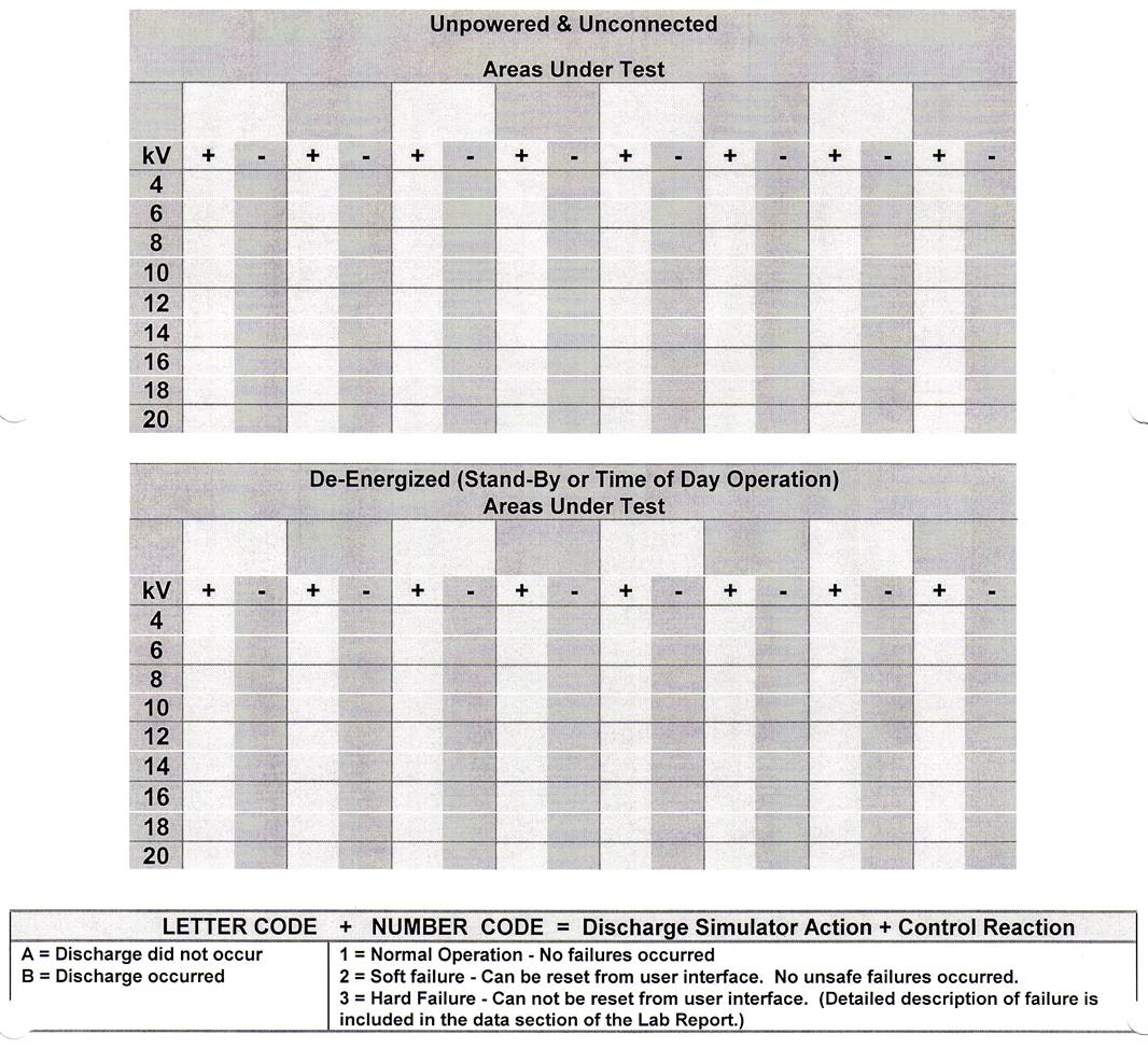
Example of data table for Electrostatic Discharge Test
APPENDIX B
UL RELAY CONTACT TEST CRITERIA
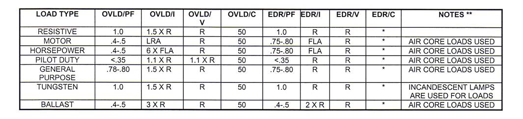
* - 6K, 10K, 30K, 100K, 250K – depending on application.
** - Actual loads can be used in lieu of using artificial loads.
OVLD - OVERLOAD
EDR - ENDURANCE
PF - POWER FACTOR
V - VOLTAGE
I - CURRENT
C - CYCLES
R - RATED